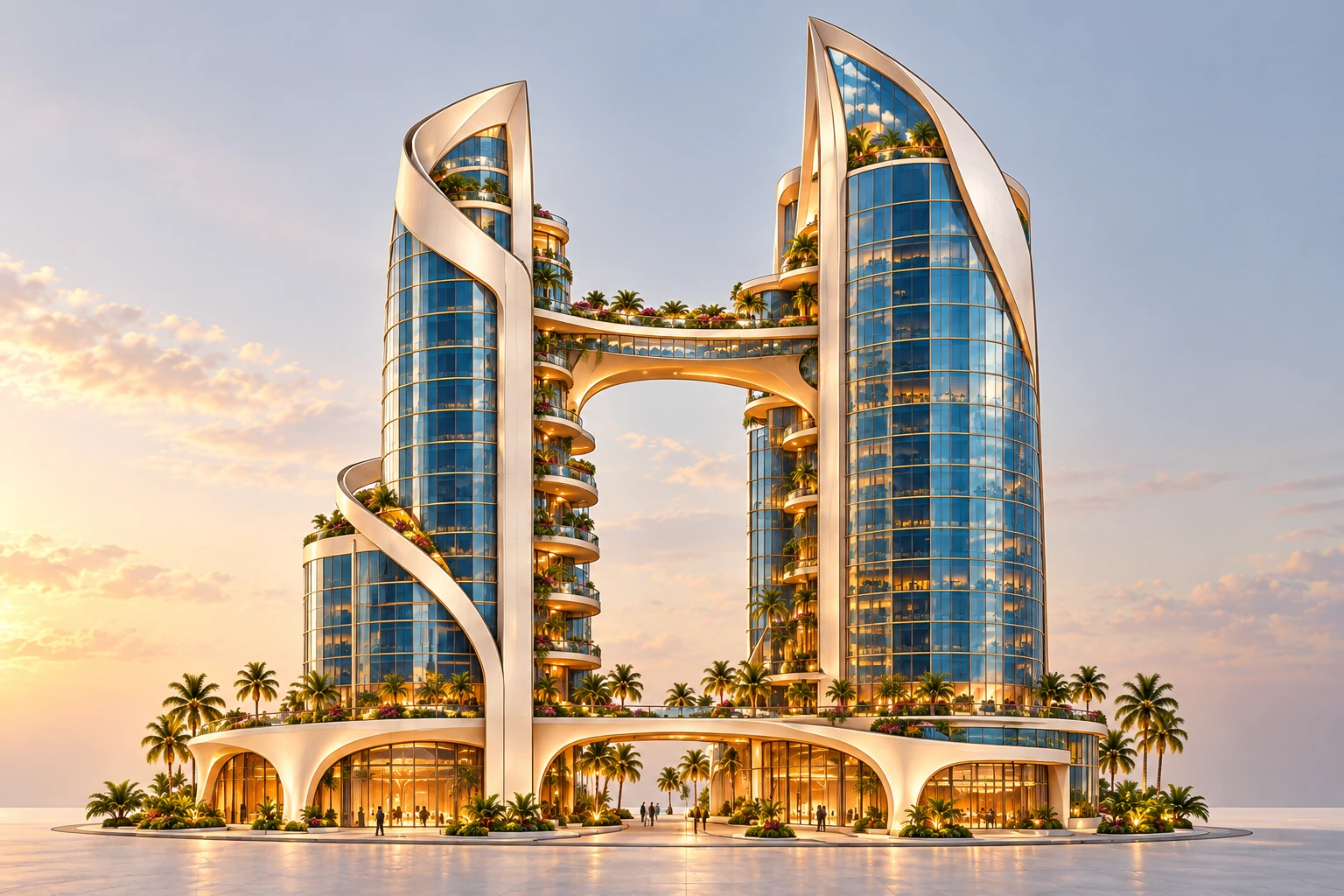
CONCEPTSplit Complex · full exteriorRecommended H1: unequal blade towers, one enclosed bridge and a low arcade base.Download image ↗
H1 is the author’s recommendation for this design pass. Creator visual and enterability selections remain open. These images are CONCEPT: they have no shared authored model, saved physical cameras or metric-fit evidence.
Evidence / interpretation / recommendation
Read the sources for different jobs.
The named catalogue card controls the complete silhouette; the closer garden-bridge render informs materials and local detail. They differ in tower balance, bridge topology and base coverage. H1 makes that conflict explicit.
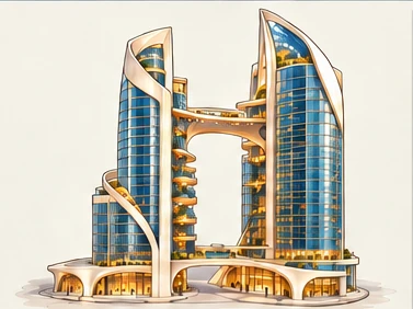
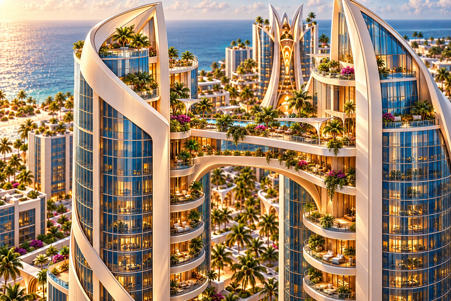
SOURCE REFERENCES1 · named Split Complex catalogue referenceAsymmetric complete identity: shorter/slimmer left blade, taller/broader right blade, open slot, one dominant bridge and low base. Source concept; not to common scale.Download image ↗SOURCE REFERENCES2 · garden-bridge close referenceBlue curved glazing, warm ivory, amber interiors and planting. The cropped render suggests stacked amenity/bridge treatment and does not resolve the full base.Download image ↗
Decision
Catalogue / S1
Close render / S2
Recommended H1
Tower identity
Distinct small/slim left and taller/broader right blades.
Cropped perspective makes the two masses read more similarly substantial.
Keep the catalogue asymmetry; no image-derived height ratio.
Bridge
One visually dominant slim arched connection.
Planted upper span with pool/shade and a lower arched partly enclosed span.
One enclosed gallery body with a level walking surface, arched underside and scenic planted roof.
Ground edge
Low arcade base and open central slot.
The complete base is outside the crop.
Low shared arcade ribbon, clear central ground passage and separate controlled lobby threshold.
Finish
Blade profiles and ivory ribbon establish identity.
Curved blue glazing, amber light and integrated planting give local vocabulary.
Carry the finish family without copying an added amenity deck or Crown Landmark’s crown.
H1 · Catalog-led asymmetric blades with one planted-roof bridge gallery
Retain the card's massing and one dominant bridge silhouette. Develop one enclosed crossing gallery inside a compact ivory bridge body, with a planted nonplayable roof and an arched soffit/haunch. Both tower landings meet one proposed crossing datum. The planted roof is not a second public bridge deck.
The bridge is one body.
one candidate accessible crossing level; exact elevation and floor IDs unset
level crossing between landing thresholds; the visible arch is a soffit/haunch expression, not an arched walking floor
scenic planting only in R01; maintenance access deferred, no public roof route
Make the junctions legible.
short recessed landing vestibule at each inner tower face; uninterrupted clear route from core landing to gallery; no balcony rail or fin crossing a threshold
one low shared arcade ribbon at the tower feet, with a generous open central ground passage and separate lobby thresholds; no enclosed mall
For concept comparison only, front means the open-gap catalog side; left/right follow a viewer facing that side. This is not north or district orientation.
The gallery, the junctions, the arrival.
The exterior above and these detail studies explore the same recommendation. Generated details remain interpretations; they are not matching views rendered from one verified model.
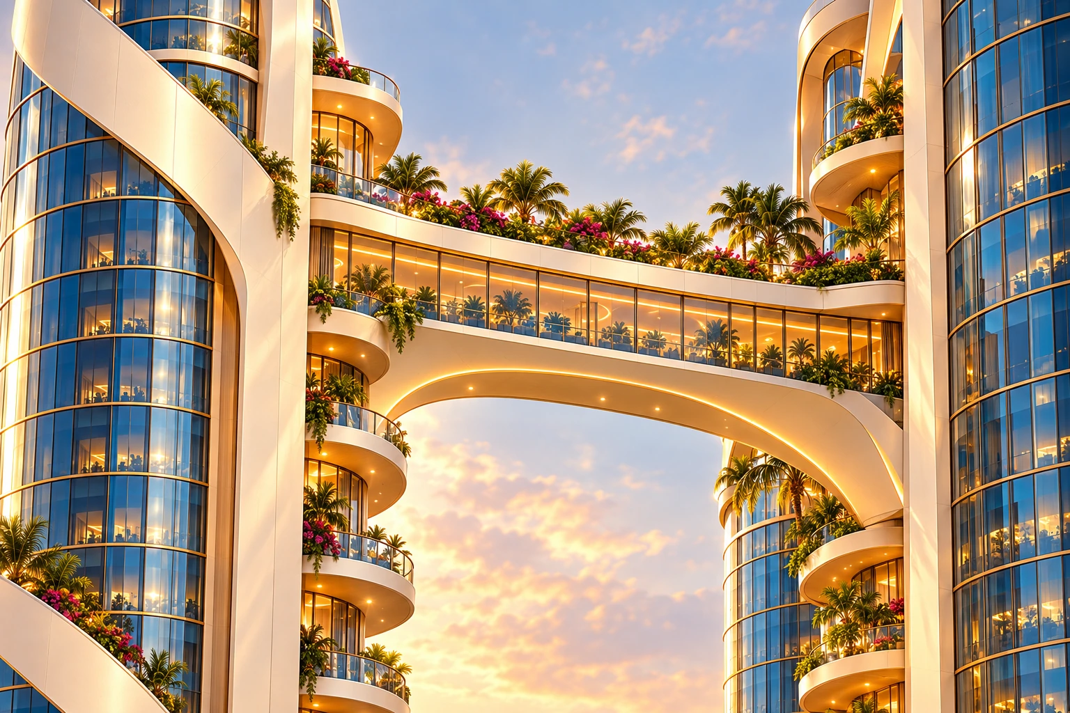
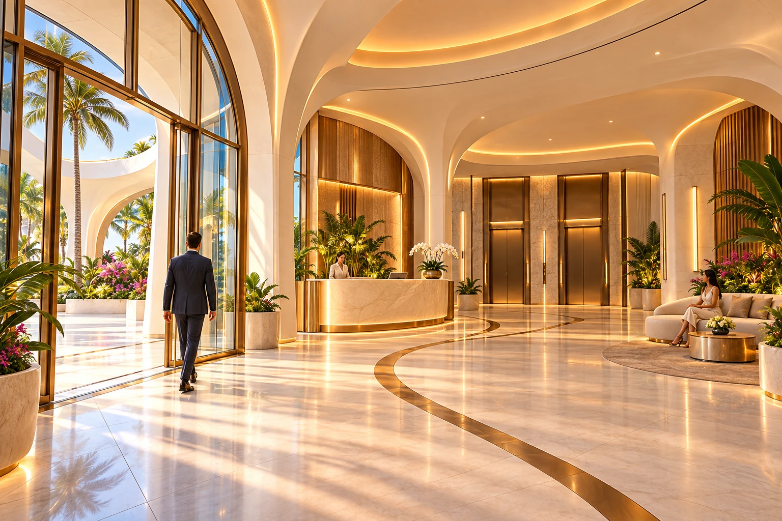
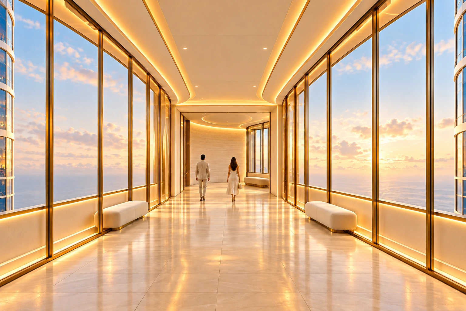
CONCEPTOne bridge body · scenic planted roofExterior connection study: enclosed gallery beneath planting, with an arched underside. The roof is not selected for player access.Download image ↗CONCEPTLeft arrival · one compact lobbyProposed single lobby with reception, an unobstructed route and concept lift portals. Other rooms and the right lobby remain deferred.Download image ↗CONCEPTCrossing gallery · enclosed receiving landingCorrected gallery concept with a level-looking central route and a visible receiving vestibule within the far tower.Download image ↗
Proposed / no whole-tower interior
Choose the journey before the rooms.
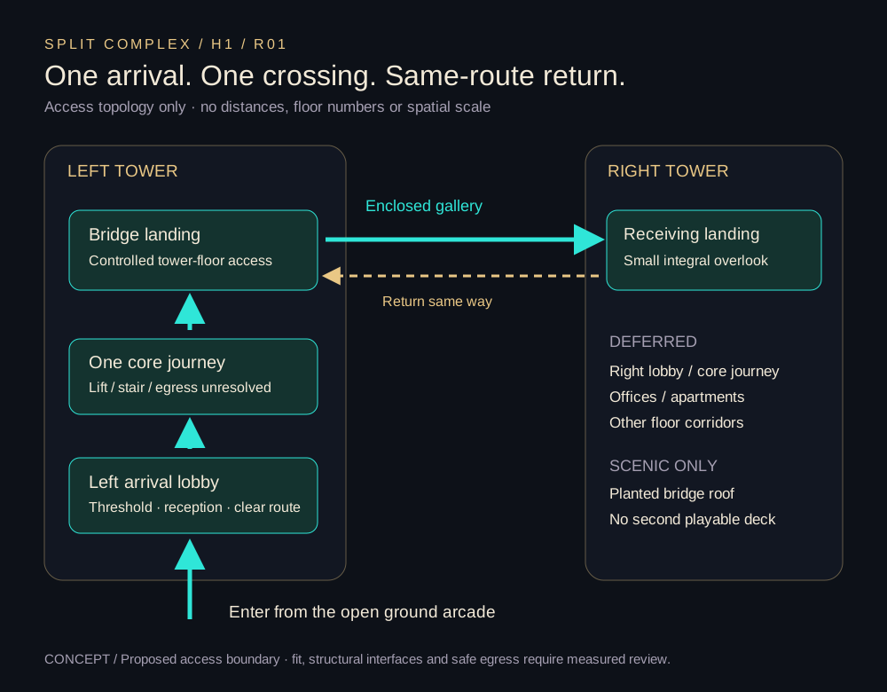
FUNCTIONAL DIAGRAMOne short route, clear stop points.Proposed relationships only. This is a semantic access diagram, not a measured plan, floor schedule or egress approval.Download editable SVG ↗
Follow the selected boundary.
left external arcade threshold
left compact arrival lobby
left core journey/interface
left bridge landing
enclosed bridge gallery
right receiving landing with compact overlook bay
return through the same gallery, left core and left lobby
Maintain a clear continuous public route with same-route return. Controlled doors separate unmodeled tower floors and staff/service zones. Both exterior tower thresholds may be visible; a visible right threshold does not imply a developed right lobby. Lift/stair, door and safe egress behavior remain test requirements.
Stop at the controlled doors.
right arrival lobby interior and right core journey
typical office floors
residential units
full tower interiors
all intermediate lift stops and floor corridors
roof pavilion interiors
bridge-roof garden gameplay
pool and shade-sail amenity deck
restaurants or retail fit-outs
basements and parking
plant rooms and service rooms beyond interface reservations
Crown Landmark council/diplomacy rooms
named story rooms
Study one left core journey from the lobby to the bridge. Reserve one core per tower toward the inner/rear side in the overall concept; the right core and additional egress remain future geometric/technical reservations, not a second interior commitment. Proposed lift plus protected stair continuity must be resolved by later plan/section and engineering review; no measured core fit or working lift is claimed.
diagram labels are functional placeholders; no issued room schedule, metric floor schedule or authoritative level IDs are created
What the next handoff must resolve.
Measured fit / next evidence
Open the technical questions and owners
Question
Evidence needed
Owner
Creator design/scope selection
Review H1 images and bounded route; record selected authority, any changes, enterability and whether a garden route is desired later.
Legend
Massing and metric scale
Author an asymmetric envelope and separate tower extents in the existing per-asset dimension contract. Establish a scale basis; no dimensions from perspective pixel ratios.
Ground/bridge plans and vertical section through both reserved cores, with the left journey and far receiving landing developed to the selected scope; level schedule, future lift/stair continuity, landing openings and usable clearances. Matching bridge datum need not imply matching floor numbers; right core/lobby interiors remain deferred.
layout/model author with Quik
Bridge structure and landing fit
One future connection record for both ends; span, bearing zones, movement, structure/fin intrusions, level walking surface, headroom and roof build-up; prove compact H1 body can contain the route.
layout/model author and technical reviewer
Access and egress
Continuous candidate public route, door operation, protected routes and lift/stair relationships; later real collision, character/camera and traversal evidence. A diagram is not egress approval.
layout author and Quik; design review by Legend
Podium and entrance
Resolve depth, central open passage, continuous arcade edge, separate lobby thresholds and core approach in authored plan and section; verify furniture and door clearances.
asset package author
Placement and external view
Selected parcel, shared metric frame, front/north convention, ground datum, access interfaces and model-derived window views. No location inferred from the close render background.
Legend with district/layout author
Engine and production release
Pilot feedback, actual versions, measured model/import, collision/navigation, materials and performance plus scoped creator/technical review. Foundation hold is not released by H1.
Quik with package reviewers
Concept publication does not release authoritative-world construction. Select the visual direction and bounded use, then resolve the existing dimension contract, shell/route fit and actual isolated test evidence.
Decision trail
Alternatives set aside for this pass
Literal close-render two-deck garden/pool bridge with two major spans. Conflicts with the catalog's slim single connection and adds a separate amenity route, level/egress obligations and planting/pool scope before basic fit is known.
Near-equal or mirrored tower pair. Loses the catalog's named asymmetric identity; cropped perspective does not authorize the change.
Bare thin exterior bridge with no enclosed route. Could preserve the card's silhouette, but does not provide the selected sheltered lobby-to-bridge route or carry the useful close-render material experience. Retain as a fallback if H1 cannot fit.
Treat generated Concept A as the geometry master. Its geometry has no authored metric model or saved cameras; promoting it would compound generated drift.
Copy Crown Landmark entrance or crown onto the gap. Erases the Split Complex silhouette and uses another asset's reference beyond its material/quality role.
Expand immediately to full Tier C office/residential floors. The starter proposes these kits but selects none; a bounded lobby/gallery route must establish useful relationships first.
Develop both lobbies and a complete two-core through-route in R01. The source program proposes paired lobbies, but the first selected concept journey needs one arrival, crossing and receiving landing only. Reserve the far core/egress relationship without committing a second interior lobby.
Sources, decisions and image records.
S1-CATALOG · 22-Crown_Key_Final_Card_Set.zip ↗ identity, asymmetric overall silhouette, open-gap relationship, one dominant elevated connection and low arcade base
Unlisted production planning · public by link · noindex. Every new visual remains CONCEPT. Original-source correspondence does not establish byte identity or spatial alignment.
Unequal tower hierarchy, wrapping left ribbon, pointed right sail, central gap and open ground passage are legible.
One enclosed high bridge body is shown beneath scenic roof planting.
Open: Rear geometry, building dimensions, levels and exact bridge attachments are unresolved.; Planting is heavier than the restrained brief; quantity remains a later landscape decision.
One glazed bridge body with arched soffit is legible.
The image suggests facade attachment vocabulary without proving it.
Open: Glazed vestibule/door interfaces disappear into tower structure.; Roof planting and edge glazing can suggest accessibility; actual roof access is excluded.; Screen-space slopes are perspective, not evidence of floor grade.
Low arched ivory/amber vocabulary and visible entrance match the bounded intent.
Reception and seating remain to the sides of the apparent main route.
Open: Depicted lift-door count is illustrative, not a core/lift schedule.; Stairs, egress, usable clearances and facade containment are not demonstrated.
Corrected far endpoint now reads as an enclosed receiving space.
Side benches stay off the apparent central route; no second bridge floor is depicted.
Open: The far-tower envelope and threshold continuity require a measured model.; Window views are atmospheric placeholders; no actual district placement is established.; Ceiling, glazing and tower-attachment details are proposals, not verified geometry.